spColumn manual solution methods
 |
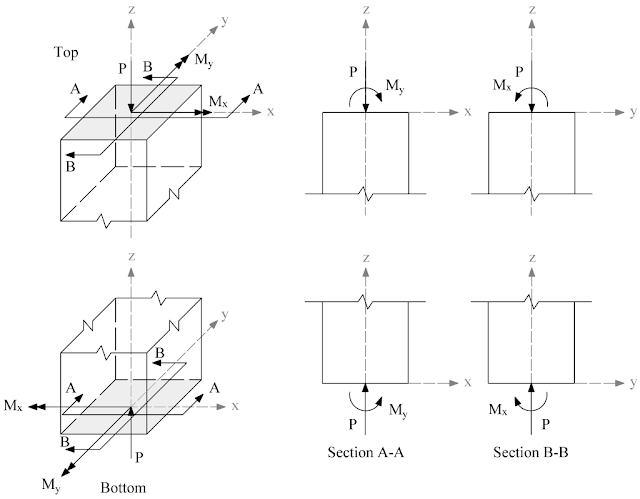
| Figure 2.1 – Positive axial force and bending moments (internal forces) |
 |
| Figure 2.2 – Positive moments loads (external forces) |
 |
| Figure 2.3 – Slenderness Input Convention |
 |
| Figure 2.4 – Analysis of Reinforced Section |
 |
| Figure 2.6 – Shapes of Factored (Design) P-M interaction diagram for ACI Code |
 |
| Figure 2.7 – Shapes of Factored (Design) P-M interaction diagram for CSA Standard |
 |
| Figure 2.8 – Interaction Surface for Combined Axial Load and Biaxial Bending |
 |
| Figure 2.12 – Special Splice Requirements for Columns per Bar Stress |
For factored load combinations in Zone 1, all column bars are considered to be in compression.
For load combinations in Zone 2 of the figure, bar stress on the tension face of the column is considered to vary from zero to 0.5fy in tension.
For load combinations in Zone 3, bar stress on the tension face is considered to be greater than 0.5fy in tension.
Type of lap splice to be used will then depend on which zone, or zones, all factored load combinations considered in the design of the column are located.
The designer need only locate the factored load combinations on the interaction diagram for the column and bars selected in the design to determine type of lap splice required.
Use of the interaction diagram in this manner will greatly facilitate the design of column bar splices.
zone 1의 계수 하중 조합의 경우, 모든 기둥 철근은 압축 상태인 것으로 간주됩니다.
그림의 zone 2에 있는 하중 조합의 경우, 기둥의 인장면에 대한 철근 응력은 인장력이 0에서 0.5fy까지 변하는 것으로 간주됩니다.
zone 3의 하중 조합의 경우, 인장면의 철근 응력은 인장 상태에서 0.5fy보다 큰 것으로 간주됩니다.
사용할 겹이음 유형은 기둥 설계에서 고려된 모든 요소 하중 조합이 어느 구역에 위치 하는지에 따라 달라집니다.
설계자는 설계에서 선택한 기둥과 철근의 상호 작용 다이어그램에서 계수 하중 조합을 찾아 필요한 겹이음 유형을 결정하기만 하면 됩니다.
이러한 방식으로 상호 작용 다이어그램을 사용하면 기둥 철근 겹이음 설계가 매우 용이해집니다.
출처 : spColumn manual


댓글
댓글 쓰기